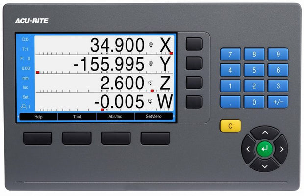
DRO300 Digital Readout
The most complete digital readout system in the machine tool marketplace, the DRO300 has full part program capability, 99 tool offsets and multiple DRO displays along with standard input/output capability and edgefinder probe support all on an easy to read 7-inch color display. Designed and manufactured in the USA, ACU-RITE readouts are the first choice for machine tool builders and users alike.
Milling Specific Features
- Bolt hole pattern calculations with graphics (full and partial circles/linear patterns)
- Centerline calculation enables you to establish work piece zero and midpoints
- Edge finder/touch probe input
- I/O (option)
Turning Specific Features
- Lock axis feature
- Instant radius/diameter conversion
- Taper Calculator
- CSS (option)
Specifications
Application: Milling, turning, grinding, boring and general purpose
Axes: 2, 3, and 4 from A to Z and Z0
Encoder inputs: TTL
Display step:
- Adjustable, max. 7 digits
- Linear axis: 1 mm to 0.0001 mm
- Angular axis: 1° to 0.001° (00° 00′ 01”)
Display:
- 3 Axes (DRO303) or 4 Axes (DRO404)
- 7-inch color widescreen (15:9)
- Resolution 800 x 480 pixels for Position Values, Dialog Messages, Input and Graphic Functions
Status display:
- Tool
- Reference point
- Operating function
- Feed rate
- ABS/INC
- mm/inch
- Stopwatch
Axis display: Standard
Common Functions:
- Multiple Display Views – DRO1, DRO2 & DRO3
- Program Storage
- Advanced Skew Compensation
- Job Clock / Stop Watch
- Feed Rate Display
- Multiple Language Support
- Absolute/Incremental
- Near-Zero Warning with Graphics
- Help function
- 99 Tool Offsets/Diameter
- Preset and Zero Reset
- 4 Function Calculator/Trig Calculator
- Instant Inch/mm Conversion
- Position-Trac™ Home Reference System
- Linear/non-linear compensation up to ±9,999 ppm
Turning Specific Functions:
- Lock Axis Feature establish tool offsets with the tool under load, resulting in reduced tool deflection
- Instant radius / diameter conversion
- Taper calculator, Vectoring
- INCLUDES Thread Assist simplify cutting metric threads on lathes with English leadscrews
Milling Specific Functions:
- Bolt-hole Pattern Calculations with Graphics (full and partial circles/linear patterns)
- Centerline Calculation establish workpiece zero and midpoints
- Edge finder/touch probe input
Cycles: Oblique line, circular arcs; only for milling, drilling, boring: circular and linear hole patterns
Error compensation:
- Axis error: Linear and nonlinear over up to 200 points
- Backlash compensation: for compensation of reversal error
Data interface: USB 2.0 type C
- For Output of Parameters to a USB Stick or PC
- For Input of Parameters, Remote Control of Keys and Commands
Switching I/O:
- Input for Edge Finder (with switching signal or contact triggering)
- Further input/outputs over the IOB 49 external input/output unit
Options:
- CSS (Constant surface speed), I/O (Input/Output)
- Multiple Scale Coupling Box
- Electronic Edgefinder
- Single-Position Tilting Base, Multiposition Holder, Mounting Frame, Protective Cover
- IB2X (allows input of 2 additional axis)
Electrical Requirements: AC 100 V to 240 V (±10 %), 50 Hz to 60 Hz (±5 %), ≤ 33 W
Operating temperature: 0° to 45º C (32º to 113º F)
Protection EN60529: IP 40 (IP 54 front panel)
Weight: ~1.9 kg
Documentation


